Close

Industrial machines and equipment often have doors, covers, panels and access hatches that need to remain securely closed during operation. At the same time, these access points may need to be released through an electrical control signal when inspection, maintenance or process access is required.
The GN 120.4 Electromechanical Locking System provides a way to combine mechanical locking with electrical control and latch-position monitoring. Designed for use with GN 115 and GN 515 latches, it locks the latch arm in the closed position and allows controlled electrical release. It can also detect whether the latch arm is in the closed position and provide this information as an electrical output signal.
The GN 120.4 is an electromechanical locking system made for latches used on doors and hatches. In simple terms, it adds electrical control to a conventional mechanical latch.
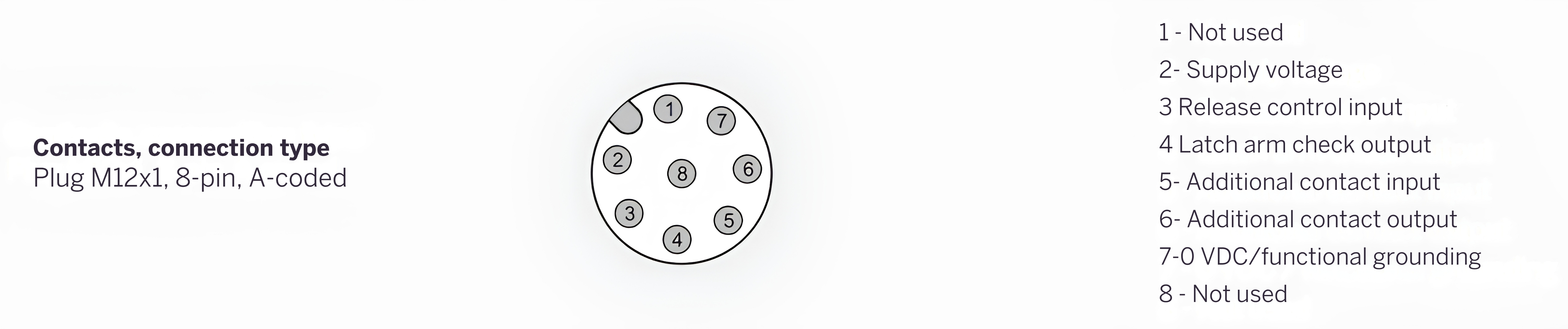
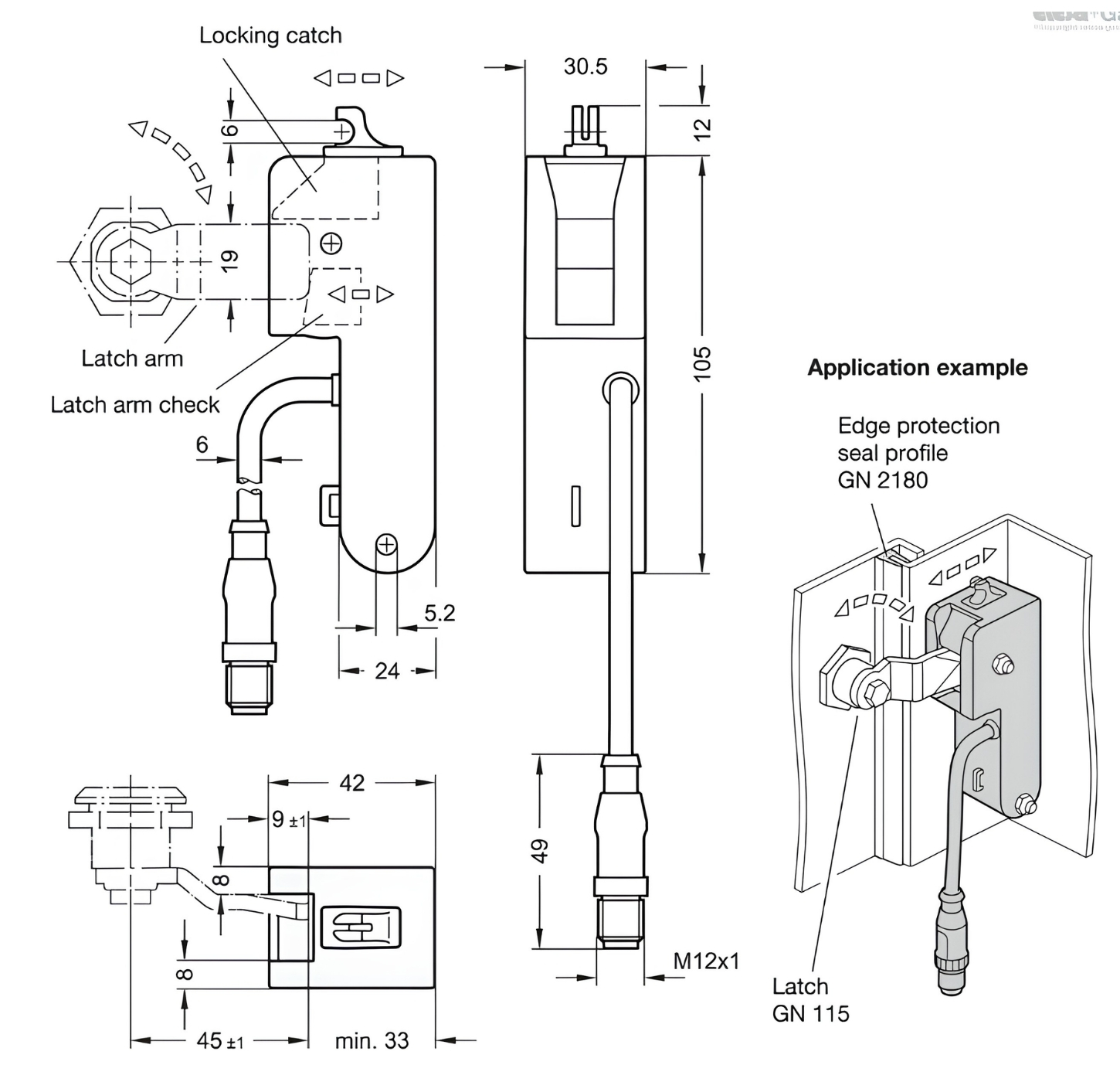
When the latch arm reaches the closed position, a spring-loaded locking catch moves into position and prevents the latch from reopening. An electrical signal can then be used to release the locking catch when access is required. The system also provides a latch-arm check, allowing the control system to determine whether the latch arm is correctly closed.
This arrangement can be useful where access to a machine enclosure or equipment compartment needs to be controlled as part of the machine sequence.
The operating sequence is straightforward.
When the latch arm is moved into the closed position, with its rotation limited to 90°, the spring-loaded locking catch engages and prevents the latch from reopening. When a high signal is applied to the unlocking control input, the locking catch is withdrawn electrically and the latch can be released. When this signal falls away, the locking catch returns to its locked position.
The system also monitors the position of the latch arm. When the latch arm is closed and the additional contacts are connected, a high signal is provided at the latch-arm check output. The additional contacts can be connected through a simple wire bridge or used with a door-position check.
This gives the machine control system information about the physical status of the latch instead of relying only on an operator's assumption that a door is closed.
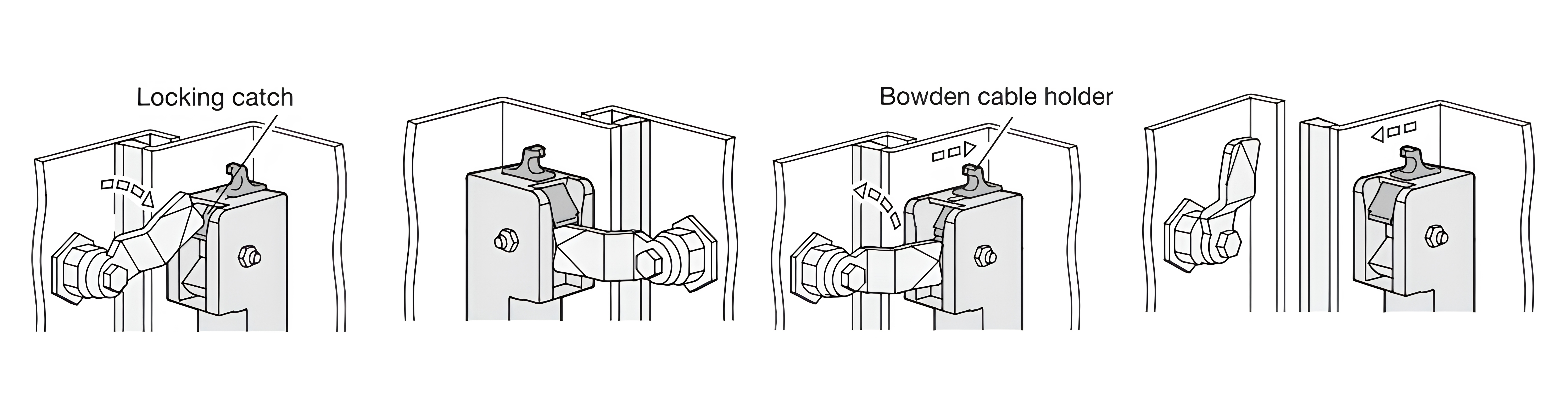
GN 120.4 is designed for 12–24 VDC supply voltage, making it suitable for integration with common industrial control systems. Its electrical connection uses an 8-pin, A-coded M12x1 connector. The connection includes the supply voltage, unlocking control input, latch-arm check output and additional contact input and output.
The unlocking control is assigned to Pin 3. A signal between 12 and 24 VDC is used to release the locking catch. The latch-arm check is available through Pin 4, while Pins 5 and 6 provide the additional contact connection.
This configuration allows the locking system to become part of a machine's electrical control logic. For example, the controller can receive information about the closed position of an access door and use that information within the machine sequence.
One practical aspect of GN 120.4 is that it can be added to existing installations using compatible GN 115 or GN 515 latches.
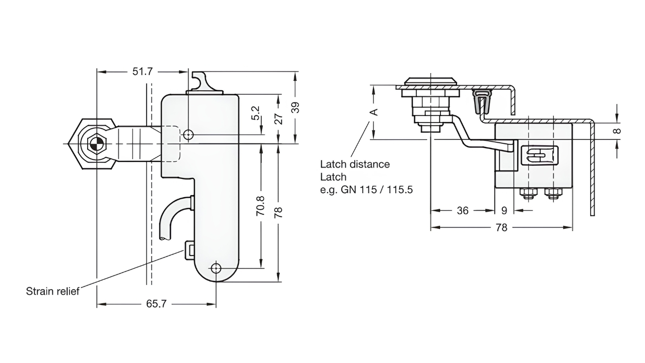
For retrofit installation, the latch distance A needs to be increased by 8 mm because of the thickness of the locking-system stop. Corresponding latch arms are available for typical latch distances.
The system can be used with left- or right-closing latches, while the locking mechanism remains concealed from the outside. This is useful when an existing machine design needs controlled locking without making major changes to the external appearance of the enclosure.
During installation, the specified hole spacing must be maintained and the recommended tightening torque of 2 Nm maximum should not be exceeded. Correct engagement depth of the latch arm is also important to avoid damage to the locking catch.
Electrical control alone may not be sufficient when equipment needs a manual release option. GN 120.4 therefore includes an emergency-release provision.
In the event of a power failure or system fault, the locking catch can be pushed back using the manual emergency release. The emergency release is also designed to accommodate a Bowden cable, allowing the release mechanism to be operated remotely through a mechanical cable arrangement.
This provides an additional mechanical release method when the normal electrical unlocking signal is unavailable.
The GN 120.4 is specified for an operating temperature range of -20°C to +60°C. It has an IP2X protection rating, with appropriate attention required for cable protection. Its maximum power consumption is specified as 120 mA, with a standby consumption of 9 mA.
The documented service life is 20 years, according to EN ISO 13849-1, with a specified B10d value of 50,000 cycles. These values provide useful reference points when evaluating the locking system as part of a machine design and maintenance plan.
The product documentation also specifies CE marking and UL Recognized status, along with listed electromagnetic compatibility standards.
The GN 120.4 can be considered for industrial equipment where controlled access to doors, hatches or enclosed areas is required. Typical applications can include machine enclosures, automated equipment, production machinery, inspection doors, access panels and process-related equipment.
Its combination of mechanical locking, electrical release and latch-position feedback is particularly relevant where the status of an access point needs to be incorporated into machine control logic.
The product documentation defines its intended use as securing doors and hatches, restricting access, protecting against possible property damage and preventing interruption of a process.
The GN 120.4 is designed with materials selected for reliable use in industrial equipment. The housing, locking catch and latch-arm check are made from glass-fibre-reinforced polyamide, specified in black, RAL 9005, with a matte finish. This construction provides a robust and functional enclosure design while maintaining a clean appearance suitable for machine installations.
For electrical connection, the system uses an M12x1 plug with a nickel-plated brass knurled screw connection, providing a secure mechanical connection for integration with the machine's control system.
The cable specification uses a PUR (polyurethane)-jacketed cable, with 8 × 0.25 mm² conductors. The cable is UL compliant according to IEC 60332-1-2913, supporting its use in industrial electrical connection applications.
The GN 120.4 range has a defined configuration based on the identification number and connection type.
The documented version is GN 120.4-42-2-A, with a width of 42 mm. Identification no. 2 specifies the version with latch-arm check, while connection type A specifies a connector plug with a 0.25 m cable. The housing, locking catch and latch-arm check are made from glass-fibre-reinforced polyamide in black, with an 8-pin M12x1 plug.
The system is suitable for both left- and right-closing latch arrangements, with the appropriate latch distance considered during installation or retrofit.
The main compatible latch components are GN 115 and GN 515, which are required for using the GN 120.4 electromechanical locking system.
For electrical connection, GN 330 cables with connector coupling are listed as an accessory. The emergency-release mechanism also provides an option for connecting a Bowden cable where a mechanical release arrangement is required.
GN 120.4 must be installed and commissioned by suitably qualified personnel. The electrical connection should be carried out by electrically trained personnel, and the operating instructions should be followed during installation and commissioning.
The product is intended for access restriction and process-related protection. It must not be used as the primary safety component for personal protection. The locking system should only be released when the function being secured no longer presents a danger.
The operating instructions specify that the system should be function-tested regularly, at least every six months, with shorter intervals recommended where switching frequency is high.
The GN 120.4 Electromechanical Locking System combines mechanical latch locking, electrical release and latch-position monitoring in one compact arrangement. Its compatibility with GN 115 and GN 515 latches, 12–24 VDC electrical control, M12 connection, emergency-release option and retrofit capability make its operating principle suitable for controlled access applications in industrial machinery.
For machine design, the key consideration is the complete locking arrangement: correct latch selection, required 8 mm adjustment for retrofit applications, electrical integration, cable protection and the intended safety function of the machine. Used within its specified operating conditions, GN 120.4 provides a structured method for controlling and monitoring access points on industrial equipment.
Technical data sheets, dimensional drawings, and 3D CAD files for GN 120.4 variants are available from elesa-ganter.in. For specification support and lead-time information, contact at offers@elesa-ganter.in
Headquarter:
marketing@elesa-ganter.in | +91-120-4726666