Specification
Types
- Type SA: Thrust pin steel, without seal
- Type KA: Thrust pin plastic, without seal
- Type SB: Thrust pin steel, with seal
- Type KB: Thrust pin plastic, with seal
Housing
Aluminum
Plain
Thrust pin
Steel for type SA / SB
- Zinc plated, blue passivated
Plastic for type KA / KB
Polyacetal (POM)
Thrust spring
Stainless steel AISI 301
Spring steel blackened
Spring steel zinc plated, blue passivated
Seal
Chloroprene rubber (CR)
Information
Spring loaded side thrust pins GN 715 are versatile and practical elements for holding, positioning and clamping of workpieces.
They eliminate costly alternatives, are space saving and easy to install. The knurled body requires only a hole tolerance of H8.
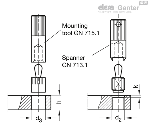
For mounting the side thrust pins a suitable mounting tool GN 715.1 is available (see table).
Technical and assembly instructions
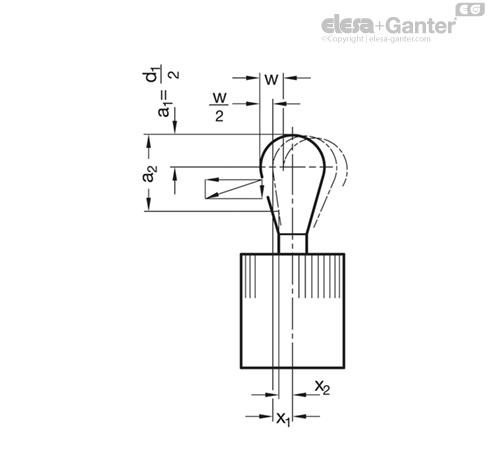
w = Movement of pin
F = Side thrust in N
initial thrust = F0
end thrust = 1.1 x F0
a2-a1 = Clamping range for workpiece
x = distance centre line – thrust point at w2
x1 for highest thrust point (a1)
x2 for lowest thrust point (a2)
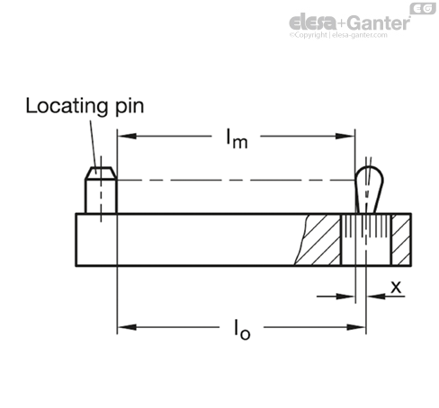
l0 = Distance end stop – bore of thrust bush
l0 = lm + x
lm = Average length of workpiece lmax. + lmin./2
For contact points (workpiece height) between a1 and
a2 a value for x has to be used lying between x1 and
x2 (interpolation).
By observing the above values the full movement of the side thrust pin will be available to cover the tolerance of the workpiece.
For inserting the side thrust pins the use of a mounting tool GN 715.1 or spanner GN 713.1 is recommended.
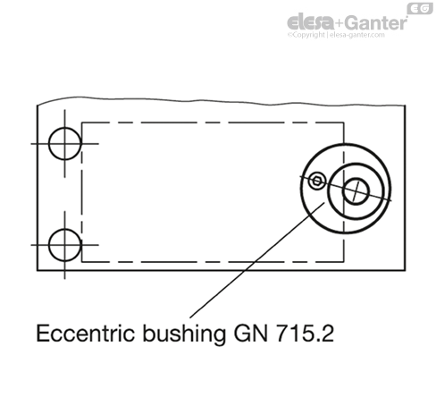
Eccentric bushes GN 715.2 are tooling accessory for GN 714 /GN 715. They enable a precise optimum setting of side thrust pins. This allows an adjustment to l0 to accommodate for instance a larger tolerance range on a workpiece.