Close

HCK-E
HCK-E
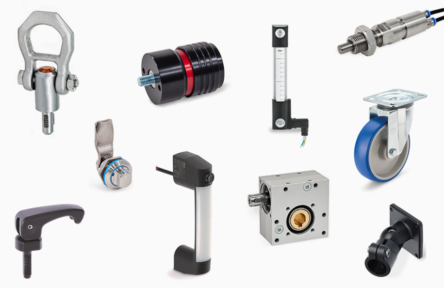
Electrical level indicators
with MIN level electrical sensor
with MIN level electrical sensor
Main specifications
Main specifications
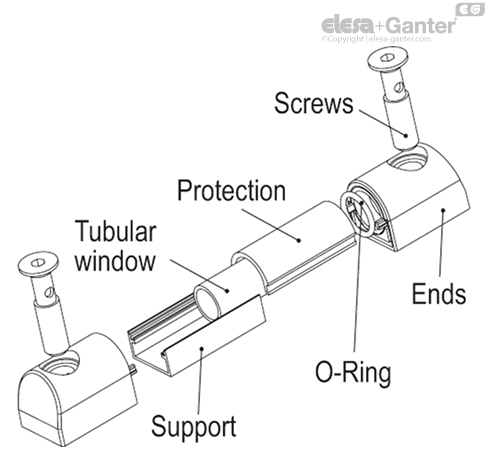
Assembly ends
Glass-fibre reinforced polyamide based (PA) technopolymer, black colour.
Support
Aluminium in natural colour.
Graduated contrast screen
White lacquered aluminium. It can be taken out before assembly to allow the insertion of level lines or words.
Float
Technopolymer, black colour, with a built-in magnetic element to activate the electric contact when the float reaches the contact threshold located at about 55 mm above the axis of the lower screw (data referred to mineral oil type CB68, according to ISO 3498, temperature 23°C).
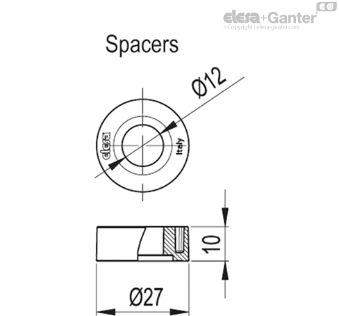
Spacer sleeves
In polyamide based (PA) technopolymer. Essential in cases where the reservoir is made out of ferromagnetic material in order to prevent the interaction between the magnet and the metal mass of the reservoir.
Bracket with male connector
Perfectly watertight, incorporating the relay (reed) with two output conductors (NO and NC version) or three conductors (SW version).
- DIN 43650 C connector in glass-fibre reinforced polyamide based (PA) technopolymer, black colour.
- 4-pole M12x1 connector, with threading in glass-fibre reinforced polyamide based (PA) technopolymer certified self-extinguishing UL-94-V0, black colour, matte finish.
For a correct assembly see Warnings.
Female connector (DIN 43650 C)
With built-in cable gland and contact holder. Front or axial output (high or low) ensuring protection against water sprays (protection class IP 65 according to table EN 60529).
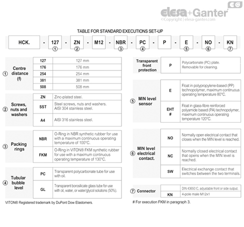
Standard executions
See configuration table.
General information
Features and performances
The HCK-E level indicator with lateral connector output allows the level of intervention of the sensor to be minimised.
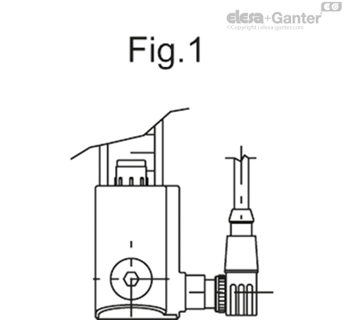
In case of use of an extension with angled connector, the direction of the cable output is shown in Fig.1.
Technical data
In laboratory tests carried out for a relatively limited time with the following liquids at a temperature of 23° C: mineral oil type CB68 (according to ISO 3498) for HCK, mineral oil type CB68 (according to ISO 3498) water or water/glycol-based solutions ( 50%) for HCK-GL, the resistance values were much higher than 35 bar.
For use with fluids other than mineral oils and under particular different pressure and temperature conditions, please contact ELESA Technical Department.
In any case we suggest to verify the suitability of the product under the actual working conditions.
Electrical features
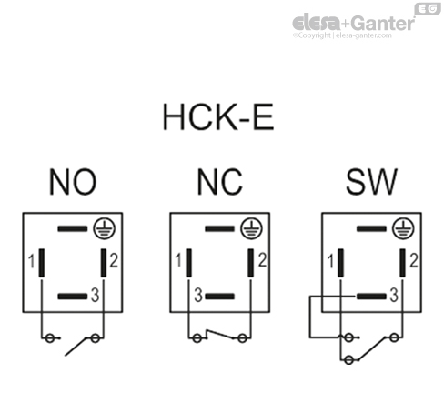
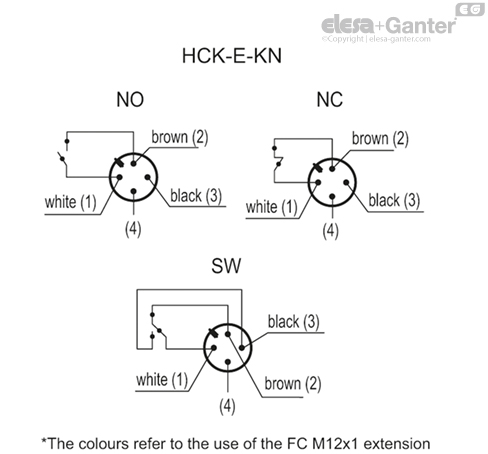
Functioning of the MIN level electrical sensor
- NO: the electrical contact closes on reaching the minimum level.
- NC: the electrical contact is opened when it reaches the minimum level.
- SW (change-over electrical contact): the electrical contact switches between the two terminals.
| HCK-E - HCK-E-KN | ||
| Electrical features | MIN level sensor | |
| Power supply | AC/DC | |
| Electric contacts | NO normally open NC normally closed SW change-over contact | |
| Maximum applicable voltage | NO: 140 Vac, 200 Vdc | DIN 43650 C |
| NC: 140Vac, 150 Vdc | ||
| SW: 140Vac, 150 Vdc | ||
| 30 Vac, 30 Vdc | KN | |
| Voltage range (Type KN) | <30 Vac, <30 Vdc | |
| Maximum switching current | 1 A | |
| Maximum current | NO: 1.2A NC: 2A SW: 2A | |
| Maximum commutable power | NO: 10 Va NC: 20 Va SW: 20 Va | |
| Cable gland (only HCK-E) | Pg 7 (for cables in sheath with Ø 6 or 7 mm) | |
| Conductors cross-section (only HCK-E) | Max. 1.5 mm2 | |
| Connector (only HCK-E-KN) | M12x1 | |
| Do not mount this indicator in proximity to magnetic fields. | ||
Other executions
Special executions on request
- Column level window in transparent methylmatacrylate (PMMA) for max 70°C use.
- Polyamide based technopolymer float (from HCK.127) red colour.
- NBR float (from HCK.176) black colour with AISI 316 stainless steel spiral for special executions, viscous liquids, high temperatures.
- Indicators with level visibility (quota) up to 1429 mm and fixing holes with centre distance (quota f) up to 1500 mm.
- Packing rings in special material depending on the customer's needs.
- Special screw with nickel-plated brass tap to be fitted to the lower assembly end for any maintenance operation requiring the indicator exclusion.
Accessories on request
Accessories on request
FC.M12x1: extensions with 4 pole M12 female axial connector.
Instructions of use
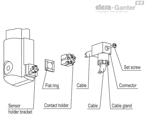
Female connector assembly instructions
- Remove the connector from the indicator by unscrewing the set screw placed on the connector, take the contact holders out and loosen the cable gland.
- Insert the cable into the connector (standard connector) and connect the wires to terminals 1 and 2 (NO and NC versions) or 1, 2 and 3 (SW version) of the contact holder. Press fit the contact holder into the connector in the desired position.
- Screw the connectors to the indicator and then tighten the cable glands.
/RedirectToProductView?storeId=10155&langId=-1&catalogId=11551&getCategoryPadre=true&=
Ask and we will answer as fast as possible
*Mandatory field
Your request was sent and will be answered as fast as possible.
Error
These products could be interesting for you as well