Close


GN 1460
GN 1460
Telescopic Slides
Stainless Steel, with Full Extension, Load Capacity up to 1000 N
- Technical Data Overview of Types Telescopic Slides_EN.pdf
- Technical Data Technical Information Telescopic Slides_EN.pdf
- Technical Data Mounting Options Telescopic Slides_EN.pdf
- Technical Data Mounting Information Telescopic Slides_EN.pdf
- Technical Data General Notes Telescopic Slides_EN.pdf
- Technical Data Component Options Telescopic Slides_EN.pdf
- Technical Data Properties_Stainless_Steel.pdf
- Catalogues
Stainless Steel, with Full Extension, Load Capacity up to 1000 N
Specification
Specification
Type
- Type F: With rubber stop, locking device in back, detach function
Identification no.
- No. 2: Mounting using countersunk holes
Slide profile / Bearings / Ball cage
Stainless steel AISI 304 NI
Rubber stop
Plastic
Detach function
Plastic
Lubricant
Roller bearing grease, FDA-compliant (NSF H1)
Operating temperature -20 °C to +100 °C
Information
Telescopic slides GN 1460 are installed vertically and in pairs. The stroke reaches ≈ 100 % of the nominal length l1 (full extension).
The telescopic slides are delivered in pairs. They can be installed on the extension on either the left or right side due to the mechanics. All mounting holes are easy to reach through auxiliary holes. Only the fastening holes are shown, but other production-related holes may be present.
On request
- Other lengths and hole spacing
- Other attachment options
Technical Information
Mounting Holes
Mounting Holes - Outer Slide
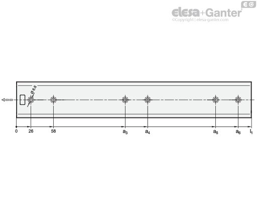
| l1 | a3 | a4 | a5 | a6 |
| 250 | 168 | 200 | - | - |
| 300 | 218 | 250 | - | - |
| 350 | 250 | 282 | - | - |
| 400 | 186 | 218 | 314 | 346 |
| 450 | 218 | 250 | 378 | 410 |
| 500 | 218 | 250 | 410 | 442 |
| 550 | 282 | 314 | 474 | 506 |
| 600 | 282 | 314 | 506 | 538 |
| 650 | 314 | 346 | 570 | 602 |
| 700 | 314 | 346 | 605 | 634 |
| 750 | 346 | 378 | 666 | 698 |
| 800 | 378 | 410 | 698 | 730 |
Mounting Holes - Inner Slide

| l1 | i3 | i4 | i5 | i6 |
| 250 | 168 | 200 | - | - |
| 300 | 218 | 250 | - | - |
| 350 | 250 | 282 | - | - |
| 400 | 154 | 186 | 314 | 346 |
| 450 | 154 | 186 | 378 | 410 |
| 500 | 186 | 218 | 410 | 442 |
| 550 | 250 | 282 | 474 | 506 |
| 600 | 250 | 282 | 506 | 538 |
| 650 | 282 | 314 | 570 | 602 |
| 700 | 314 | 346 | 602 | 634 |
| 750 | 346 | 378 | 666 | 698 |
| 800 | 346 | 378 | 698 | 730 |
Mounting Screws
For the said loading forces FS to be absorbed reliably in the surrounding structure, all available countersunk holes of the outer and inner slide must be used. Failure to use fastening screws reduces the specified load capacity accordingly. The following screws can be used for mounting:
| Designation - standard | Outer slide | Inner slide |
| Hex socket countersunk head screw DIN 7991 | M 5 | M 5 |
| Countersunk screw, Phillips DIN 965 | M 5 | M 5 |
| Countersunk screw, Phillips DIN 7997 | Size 5 | Size 5 |
Rubber Stop, Locking Device in Back
The rubber stops of type F dampen the impact of the slide in the respective end position. This feature minimizes noise development and increases the lifespan. Attached to the slides in a partially concealed, partially visible manner, the stops meet each of the requirements in regard to shape, material, and hardness.
The rubber stop takes on also a locking function in the back stop position. This feature is noticeable through a slight resistance on opening and closing the slide.
If larger static or dynamic loads occur in the direction of extension, they should be absorbed by external stop elements.
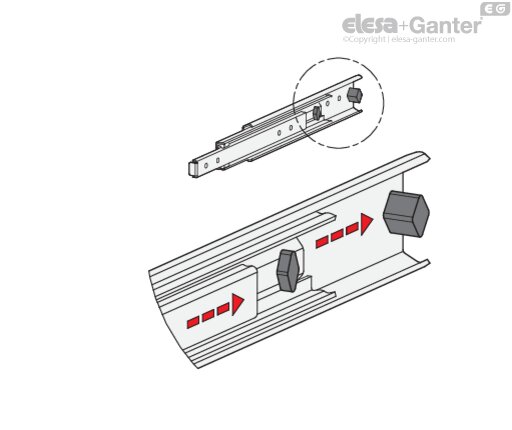
Detach Function
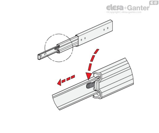
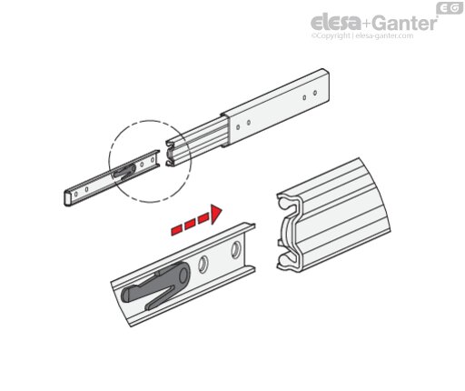
Type F has additionally a detach function through which the extension slides can be completely separated from one another in the area of the middle and inner slide. This feature not only facilitates mounting. It also allows the extension to be quickly removed, for example, when frequent maintenance work is performed on the components located behind.
The telescopic slide can be quickly and easily detached in the extracted position through activation of the release lever, allowing the inner slide to be removed from the front.
For reattaching the slides, the ball cages need to be moved to the front end position. Then the inner slide is inserted to the back end stop where it locks into place automatically.
The protected arrangement of the release mechanism prevents accidental detachment of the slide.
/RedirectToProductView?storeId=10155&langId=-1&catalogId=11551&getCategoryPadre=true&=

Ask and we will answer as fast as possible
*Mandatory field
Your request was sent and will be answered as fast as possible.
Error
These products could be interesting for you as well